Friday, 28 June 2013

So did the mast work ?

So, the question needs to be asked......

Did it work ?

Well the answer is ( I Think ) a resounding yes :)

The reason for no posts recently (other than being busy at work) is that I have entered two yes two contests.
Ground Level (more or less!)

The Practical Wireless 144Mhz low power and the 50Mhz Trophy contest.

Here are some pictures of the 144Mhz set-up the first one is it ready to be pumped up and the second one is it fully pumped up and ready to use.

Did it work - well I think the answer is definitely yes ! I ended up with 77 contacts (remember this is a low power - in this case 3W) contest, the furthest away being GI4 which is 419Km away, also some first for me with my first GM station on 144Mhz, as well as my first Isle Of Man station and my first French station on two - for me a brilliant personal result - I've entered the contest but as it is predominantly a portable contest I'm unsure how a fixed station like myself will be placed, several portable stations I worked had very large serial numbers !!!!
Final Height - and in use.

The best part was 30 minutes after the contest had finished, I had dismantled the antenna, the mast was 'let down' and stored away and everything was back to a 'normal' garden.

So it absolutely hit the mark with regard to the design spec that I set myself on both the time to get ready and the time to remove it.

It was so successful that I decided I would try the next weekend the 50Mhz Trophy Contest  (RSGB), This is a 24 hour contest, but does have a six hour fixed station section (6F) that seemed reasonable.

So I removed the 6M antenna from the loft space (this is a dual band 6M/4M with 3 elements for 6M and 4 for 4M).  I used the same arrangement that I  used for the previous weekends 144Mhz contest, but learnt that I could use the step ladder to aid the mounting of the rotator and antenna, and help make this truly a 'one man' operation. Here are a couple of pictures of the antenna in place and at the full height.


50/70Mhz Dual Band Antenna @ full height

As you can see it looks good (well I think so!), it was pretty gusty and so this time I took the precaution of putting two guys in the direction of the prevailing wind.

I'm pretty sure it didn't need it as it wasn't moving at all before I deployed them, but better safe than sorry.

Again, did it work ?

Well I think again a resounding yes !

I worked 38 stations, with a combined score of 340825 (claimed) , conditions were very poor, with only one or two sporadic E openings, my best DX was ES1MM/2 in  locator KO59DI this is a distance of 2045km. I also worked my first GM on 6M, and into Iceland. 


50/70Mhz Antenna close up
Whilst I was very pleased with the overall set-up and how things went the conditions were truly dire. Considering I only have a 3 element antenna and only use 100W I did pretty well, I'm currently 4th in the 6F part of the contest. Others are running larger antenna's and much more power (2 or 3 times more) so not too bad in my view.

Again the mast came down really quickly and within 25 minutes, it was back to a 'normal' garden with no mast or antenna visible.

So is the mast a success - On balance I think yes, two contest entered, both pretty convincingly - which I wouldn't have been able to without the mast. result :)

Now to up the power on 6M and get a better antenna - onwards and upwards - literally !!!!

Tuesday, 4 June 2013

Ordered my 144Mhz antenna

After all my hard work on the mast, I thought I would give it an airing in the PW 144Mhz low power contest this weekend (Sunday).


This is a low power (3W) contest and so it will be interesting to see how it goes. Of course to do this I need an antenna and so after looking around I thought I would try the 9 element 144MHz OWL Super-Light Yagi made by.innovantennas in Essex (www.innovantennas.com) to a G0KSC design.

Looks like a good gain figure and also a reasonable boom length as well. I will be picking it, as they are quite near where I am during the week, up so that I will have it ready for the weekend.

Now just to get the feeder and the rotator all sorted :) - I've got both (including the rotator cable) just got to get them all connected and sorted out. Something for Saturday I think.


Monday, 3 June 2013

50Mhz - what a band !

You've got to love it !

For most of the week, well all of it actually I'm located away from home and recently i've put one my FT817ND's in the flat so I can have a tune around when I feel like it.

With 50Mhz being open a lot recently I thought I'd have a quick listen when I got in from work, it was open, and unbelieveably with just the standard antenna connected to the front panel I made a contact.

It was with IC8TEM located in JN70CN - Capri Island  he was strong here (JO01IM) and gave me a 59 I returned the complement. 

That was with 2.5W (max) to a rubber duck antenna indoors -  a distance 1597Km as the crow flies

Not a record but pretty amazing really :)

73's
Chris

Sunday, 2 June 2013

Lovely weekend - more work on the mast

So last Monday (Bank Holiday) I fixed the seals in the Mast (see my last Blog post) , it was a lovely day yesterday, and so I set about putting the plan for the mast in action.

Mast, small Granddaughter, and black Lab,
and yes I know the mast's not vertical, its
just a test !!
First I got the ground mount sorted.

As discussed in my last post I used a fence post spike 600mm long, which after grinding, drilling and welding provided a great ground connection for the mast.

I then set about thinking how to make sure the mast stood vertically and safely. In the end I decided on a three legged tripod which can be taken apart when not in use, I again cut, welded and drilled three legs (adjustable using butterfly nuts - a nice touch I thought :).

;
Lovely blue skies :) 
I hammered the ground spike in the ground, and test fitted the mast, all looked good, I then test fitted the legs, a bit touch and go, but after some re-engineering on the fly, all looked good, although I couldn't find the right size butterfly nuts and so final test assembly would have to wait until Sunday.


Mast from another angle, minus
Granddaughter and dogs :)

So Sunday arrives, bright and lovely, I decide to go to the Spalding Radio Rally in the morning, where I spend a pleasant hour or so wandering around, by a couple of things, got hold of a Gigatronics power meter which needs a remote head for £25 which I think is a good buy.

Return home via hardware shop to get right size butterfly nuts and bolts, complete final assembly, and then for the first time, try it out, mast pumps up beautifully, holds up without locking it, but I lock it anyway for safety. With the tripod it's really sturdy, even in the gusty wind, a real result, even the family are impressed :)

Basically it works !,perhaps  a little 'agricultural' in engineering terms, but then I'm an electronic engineer by training not a mechanical one !!. I still have some fine tuning to do but as you can see from the pictures dotted through the blog showing the fruits of my labour it worked, any comments most welcome :) . At this rate I might make am entry into the Practical Wireless low power 144Mh contest next weekend,  if I can find a suitable 2M beam 
Mast what Mast !

To top it all of course, 6M was wide open again into Europe in the afternoon via Sporadic E, worked way down into Greece, Italy, Spain and quite 'short skip' E into Germany, France and Austria. If only I'd done this earlier I might have been using the mast with a decent 50Mhz antenna on the top !! - ohh well never mind perhaps that's only a week or two away, might be ready for the 50Mhz open contest !!!


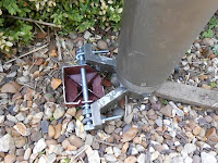
Below are a few final of pictures showing the ground mount spike / swivel and the mast in its stowed position, I haven't bothered removing it from the ground spike at the moment. Also considering if it needs to have guys as well as the tripod mount, might do so just in case, especially with a rotator and beam on top :)


Just goes to prove, where there's a will there is most definitely a way !!! 

It certainly fulfilled the design brief I set myself ...

Ground mount, mast vertical
Mast lowered and horizontal (can be removed from
ground spike if needed)

Close up of ground spike, the mast can be removed from
this by undoing the knob on top and the two silver machine
screws on the side


Monday, 27 May 2013

Bank Holiday Monday - Mast preparation :)

After my last post on 6M I got to thinking about how I could get a better antenna for 6M, and perhaps 4M and then there's always 2M as well isn't there !

I've had in my mind for several months the idea of a 'temporary' mast to enable me to quickly get some decent (perhaps 6 element 6M beam) up in the garden for weekends and contests.

The basic criteria would be -

1 - Temporary - most important after studying the planning regulations, I didn't want to apply for permission for a mast, especially as I live in a conservation village, whilst I might find antenna's pretty special others (including the xyl) might have other ideas. A 'temporary structure' is defined as one that is not permanently fixed to a building - or other structure.

2 - It must be fast to put up and take down - I want to do radio not build masts etc.!

3 - Would be high enough to get above the house from the back garden

4 - Would be able to be assembled as dis-assembled  by one person (me!)

5 -  Would have minimal impact when taken down (ie must be temporary, not visible and not a structure when taken apart)

I've been thinking about it for some time and in the end decided that an ex mod pump up mast would be best.

Not a SCAM12 - those are massive, and whilst built like the proverbial 'brick out house' they weigh a ton and are designed for a small army to assemble, so what next ?

Then I came across (again via eBay what would I do without it) a Hilomast NK9, a lot more manageable - when pumped up 9M, 2.3M when retracted, 22Kg's of head weight and it weighs approx 21KG, which whilst bulky is manageable for a lard ass like me :)

It was advertised as "possibly in need or refurbishment"  I took a punt and won it just over £100, with semi local collection, I picked it up in my 7 series - couldn't do that with a SCAM12 :)

This was autumn of last year, I got a seal pack from SMC Communications (£70+ ouch!), and then did nothing with it.

Then my 6M post |(and an upcoming 2M low power contest), and I thought I take a closer look at how I could use it.

Well after 6 hours or work, I've replaced all the seals, and now know intimately the inner
The construction of a Hilomast
(c) Hilomast (SMC)
workings of the Hilomast !! - if you've any questions just ask !

I'm was very impressed with the build quality, really good stuff, great to work on, perhaps the equivalent of a BMW or Audi in engineering terms, when I dismantled it, I discovered a hand written note on one of the upper tubes, that it was re-built in 1994, so I doubt that its been touched since then. The top section is slightly damaged, but has no effect on the use of the mast at all.

I did check before working on it and it didn't pump up at all :(  and now after working on it, it not only pumps up, but also stays up (without using the locking handles), so now all I've got to do is work out how to put together a ground mount to help me put it up, and also how guy it to make sure it doesn't fall over with the antenna's on top !!

I've already decided that the cables would be permanent from the house to ground level down the wall in a weather proof box. I've already go a method of getting cables from the loft to the outside world using the a waterproof hole in the soffit (or is it barge board) of the roof, with a removable, flying cable up the mast, including the rotator control cable, to enable quick set up, and keep things tidy.

I recon that I should be able to get it set up for weekend working (I'd have to choose the antenna obviously !) in about 45-60 minutes and then take it down in about the same.

That should give me great gives flexibility  (Contests are only at the weekend, and actually I'm only around then to play radios's), a reasonably good antenna for my favourite bands 6M,4M,2M, and no planning problems as its temporary, I can even drop it down to 7ft when I'm not using it to avoid neighbour problems.

I should be able to store the antenna vertically at the side of the house safely and so not too much disassembly should be needed, and if it does need this its a small price to pay I think.

So next step now I've got a working mast is to get the ground mount sorted out, and get the cables put in permanently. Thinking cap on, I've a few ideas already.

Sorry there's no pictures, I didn't really think until I was finished, that I'd write it up on the blog, silly me :( - I will when I do the ground mount, and of course the final result.

Now how big is a 40M three element beam (!!!) :)

73's
Chris

Sunday, 19 May 2013

6M - Truly the magic band !

I thought I would get some time in the shack today (Sunday), I've got several projects on the go, some of which I've written up on my blog - such as the TS-570DGE and several which are still on the bench (like the Ameritron 811 Linear amplifier)

I switched on the 756 PRO to see what going on, and found to my delight the 50Mhz was wide open again (it was yesterday) and so spent a very pleasant couple of hours working into France, Germany, Austria, Italy, Spain.

Heard far more than I worked - but then there is a reason......

I only run the 756Pro barefoot (100W) and my 3 element 6M beam is located in my loft !

Yes its pointed south and its in my loft - so had over 35 contacts right across Europe - not too shabby :)

I've plans for getting a better (ie external !) aerial for 50Mhz later in the summer when I can get some spare time, but in the meantime .....


A station in Italy pretty much refused to believe that my antenna was in the loft space as my signal was so good

Just proved what can be done - don't give up hope anyone who can't get an external antenna for  50Mhz when its open internal antennas really can work.

Great fun - truly 50Mhz is a magic band !!!!

Saturday, 18 May 2013

Kenowood TS-570DGE Repair - lets get started (and finished as it turns out!!)

So....

Got it home and found some time to have a closer look at it.

Sure enough, as described, everything works, but its as deaf as a post :( , the TX side is fine, giving 100W out, so that's good.

I'd already downloaded the workshop manual prior to bidding (to check what components I might need to check the circuit configuration - well its best to know what your in for isn't it :) ) and so knew where the front end components, protection diodes, bandpass filter switching diodes etc.

So removed top and bottom covers, as usual the bit I want (rx input etc) is on the 'bottom' of the radio !

I start the investigation, no obviously damaged components from the top, no smell (remember that the seller said he thought that some had transmitted into it by accident) of burnt or damaged components.

I test the protection diodes - all ok - good
I measure the switching diodes on the bandpass filters - to my surprise there are all - so a moral there never believe what you are told :)

I have a break and a think at this point, I had expected this to be the problem.

I decide that I will fall back to normal fault tracing, and so inject a strong signal into the aerial socket and start tracing.

Circuit is below for this area so you can see my work ;)


Partial TS-570DGE circuit - copyright Kenwood Communications


1 - Signal at the antenna connector on the board - yes  (CN1 above)


2 - Signal at  R2 - yes3- Signal at R2 end of L4 yes4 - Signal at tp4 - NO (!!!!!!!!)These test are a little tricky as everything is surface mount, but no real problems, so I decide to inject the 14.100Mhz signal into TP4.Result is an end stop signal on the radio.So L4 is at fault ? - remove from the PCB and yes its open circuit :) - fault number one. I temporarily jump out L4 and sure enough - receiver works perfectly, pre-amp fine, all looks great :)Whilst in this situation I give it a really good check out - seems to work perfectly, have a few short qso's all fine, so a suitable surface mount 0.25u inductor goes on the part list.Whilst checking it out I notice that the attenuator doesn't attenuate (!) , so I chase the circuit and discover that R1 (56R) is open circuit - I have a suitable surface mount resistor and so remove it and replace - Check again and now the attenuator works - result !I then check around the circuit testing voltages as per the  workshop manual - (BTW - I really like Kenwood / ICOM service manuals as the have really comprehensive voltage / voltage tables for TX and RX - Yaesu don't seem to - why is that ?)At this point I check again all the bandpass switching etc - all is fine, I notice however that on TX the voltage on the rx line should drop from ~10V to 0 - ie muting the rx line, but it doesn't - another fault.I remove the PCB (as Q2 is mounted under the board) and as I lift the board - what do I find ? a rather burnt Q2 - so its added to the component list for repair.So conclusion ? - well it must have had some RF into it I would have thought. my guess is that the attenuator was switched in and it took out the 56R resistor, then the inductor and then Q2, thankfully it was transient and so no further damage was done.Components ordered, arrived and a pleasurable 10 minute install of the inductor L4 (if you should do this watch the soldering iron on the relay !!!, then removed the board and replace Q2.Re-assemble it all, check and check again - all works perfectly.I then do a full alignment check as per the workshop manual, everything is spot on, nothing to adjust or change.I then spend a little time cleaning it up a little and then a very pleasant afternoon on 40M and 18M having so very pleasant QSO's - all works perfectly.So the conclusion;Yes there was some damage, someone (or something) did take out some front end components but whatever it was must have been pretty short lived as none of the normal protection components or bandpass switching diodes were damaged, my guess is that L4 and Q2 went, L4 going open circuit effectively acting as a fuse / protection component :)So a little time (about 2 hours fault finding) 3 faults and total component cost of £2.45 - I have a working really nice TS-570DGE  working really well - RESULT :)Now to keep or sell - I wonder ?  

Thursday, 16 May 2013

TS-570DGE Repair

Well I couldn't resist could I ?

Recently, well a few weeks ago actually, on a well known auction site, a TS-570DGE that was faulty. TX fine but RX was as deaf as a post, didn't have a good picture at all (see below)


Should I or shoudn't I  ? - surface mount doesn't frighten me, the owner hints that it might be the siwtching diodes in the bandpass filters, but then if its had higher power RF into it then who knows ?

I decide (as with all my bids) what I think its worth, place the bid and wait.

I win it for for quite a bit lower than my top limit :)

Its reasonably local, so I go and pick it up, its in excellent condition, is a DGE version, has a box with the packing, microphone, manual and power lead.

During our chat, he says that he has had the case off (bad sign) but was not impressed with all the surface mount and so didn't touch it (good sign !), he did say that when he touched around the input side of the receiver (!!!!) the receive side did pick up (it received signals!) - so might be a dodgy connection. He demonstrated that the TX side worked (it did :) ) and also that the rx side was as deaf as a post (it was !!).

He also had people email him saying this was a common fault and it was the swithcing diodes in the front end. I did some research on the net, and looked at the circuit diagram, but came up with nothing that was a 'common' fault. Yes there were faults reported and yes there are plenty of switching diodes in the from end but 'common' no.

So I pay the money, and retire home, pleased with my purchase and keen to find out what the real reason for the poor receive is.

Monday, 13 May 2013

Down East Microwave - 144-28 Transverter Repair - Helping out someone else.....

I've been very busy at work recently and so not had much time for the 811 or any of my other projects 

BUT

When I was on 40M a few weeks ago I had a really great QSO with someone that had a 144 to 28Mhz  transverter that needed repair, and I talked about some of the repairs that I do, he had a look at this blog and my QRZ.com page and well ........ I ended up offering to take a look (with no guarantee's though !!!)

When it arrived a couple of weeks  it was a top end (Down East Microwave) transverter with a 28Mhz IF, low level input (0dBm). The report was that it didn't transmit. It did a manual with it, although when I opened it up it didn't seem to match the actual layout of the board although the circuit looked pretty close !

First things first, a close visual inspection - nothing to note  here no burnt components (to the naked eye), no overloading by the look of it. The owner did  say that he thought it might have had a near miss with lightening (!!) and so I had expected the worse, but no.

I was very impressed with the build quality, absolutely superb :) here's a picture of it on the bench ;


So i powered it up (via a current limited supply) - checked the Local Oscillator, right frequency - has a wonderful temperature stabilised arrangement - worth looking at the circuit really good for frequency stability, warms the crystal up and keeps it there - very clever, i've seen it in professional kit but never in a transverter before !

Got a suitable IF transceiver (in this case a ten tec as it has a nice transverter output at the right level and does key output for the ptt) connected it up and...................

RX worked fine - injected a -127dBm 2M signal from my test set and this was easily detectable in the IF transceiver so no problems there - great news !

Checked the input level from the transverter correct at 0dBM (224mV into 50R), accroding to the manual this should give more than 10W out on 2M from the transverter.

Key down on CW (as per manual suggested setup) - nothing out into the Bird ThruLine :(
well after putting it onto the test set it was actually giving out ~300mW !!

PA block failure perhaps ?

So worked my way down (or is it up ?) the tx chain, after swtiching the 28Mhz IF signal goes through a MAR 3 MMIC amplifier to take it up from 0dBm and yes 0dBm in but -6dBm out - so the amplifier is an attenuator  :) might be a problem !

Check the voltage supply in the area / biasing and all looked reasonable - so decided to bypass the amplifier effectively making it into a higher input power transverter, injected 1W from an FT817 on 28Mhz and w and behold ~20W out on the Bird.

So a fault MAR3 MMIC, after finding the right manual it said this should be a MAR 6 anyway which was a little confusing, the owner didn't know why and had never changed it so perhaps it was built this way ?

So after chatting with the owner via email, I ordered some MAR 3 and MAR 6 MMIC's (always good to have a small stock and I didn't have any !!). 

Arrived last Friday, quick change (photo of new one installed below) a new MAR 6 was installed as per the circuit diagram (the scratches where its mounted were already there, this is where the track was cut to insert the option MMIC in the TX chain to allow lower drive levels, its detailed in the manual);


For those readers who don't know what a MMIC looks like its the small black dot with 4 legs in a star arrangement above the orange disc ceramic capacitor :)

Fired up the Ten Tec as the IF on 28Mhz and the result is shown below ;


The meter on the left is showing the RF input to the PA Hybrid at 1.6V which is 50mW (what the manual says it should be) and the output on the Bird is showing 35W - this is using CW as per the manual suggests. I set the input control (the lower blue variable resistor on the MAR6 photo)  to give the 50mW input required.

So all fixed and working, gives approx 23W on speech peeks, and the output is nice and clean - see below (apologies for the poor photo!)  each graticule block is 50Mhz and the large spike (!) is of course the 144Mhz signal.


After a few more email conversations with the owner, his IF transceiver gave a little more output than mine +10dBm (100mW) and I wanted to check that the input into the PA block hybrid didn't overload anything and so I constructed a 20dB attenuator and used a 1W input into this from an FT-817 to give 100mW and then adjusted the input resistor pot (as above) to give the right input level of 50mW.

I then gave it a really good test over several hours at that level with simulated long overs etc with breaks etc, the unit get warm but not overly so, and so I think this is fixed - result.

Now Ii've just got to post it back to the owner - hope he likes it - its certainly working better now than before !!!!

Thursday, 25 April 2013

Ameritron AL-811HXCE valves arrive

As per previous blog I got hold of some NOS - New Old Stock RCA 811A for the 811HXCE. I've already got some russian copies but wanted to get some reasonable ones for testing and have had great experience with RCA's.

They arrived, very well packed and they were better than I could have hoped, boxes a little used looking but inside original packing and lables (always a good sign !!).

Here they are (well one of the four anyway !!) :-


Tuesday, 23 April 2013

Ameritron AL-811HXCE - Components arrive

Well, the postman's been busy this week :)

Arrive home to find a small package, which contains my larger doorknob capacitors that I purchased. I was pleased to see how carefully they were packed - padded envelope and within that a small plastic box, and within that some more bubble wrap !! 

When opened, I find (somewhat confusingly !) four capacitors - the two I ordered and two extra, only after checking the packing note did I realise that the extra two were a free gift from the shipper - bonus ! 

The quality of the doorknob capacitors seem excellent, as expected these are Russian made but measure correctly and are new and unused.
Superb packing !!


Sunday, 21 April 2013

Ameritron AL-811HXCE back to life - part 5

So, having made the PCB (see part 4), now comes the time to populate it. Parts arrived fine from Farnell, and the capacitors of a similar type from another UK supplier.

I'm not keeping a total of parts spend on this - (if money was no object then I would have simply sent it for repair[no fun or challenge in that!!]  or got the bits from Ameritron in the states - look back at my earlier posts - this is not cheap!) - anyway I think as amateurs we can all improve/build on each others work, and definitely improve on commercial designs, where sometimes quality is compromised for ease of production or make slightly more money.

So wound the coils, and put the coils and 5w 100R Resistors in, and then put the braided leads on for the anode caps. 30 minutes of construction results in a new parasitic board.

Here it is -


Not too shabby really, in my humble opinion, if you consider what it was like before (look back in the blog) and now after a total rebuild, there is no comparison in my opinion, a major difference is that I hope that this one will work :) - anyway two major elements completed, the choke and the parasitic board, so onward to component improvement and rebuild, then test !!

Nearly there !

Sunday, 14 April 2013

Bringing an Ameritron AL-811HXCE back to life - part 4

So....

Rewound / rebuilt the choke (see part 3), and so now onto the parasitic board. Now this was very badly burned up, carbon in many places as you can see from the pictures (apologies about the quality of these!). The odd bits of wire coming out of either side are actually the HV feed to the 811a anodes cap and yes you've guessed it, they are badly over heated / damaged.


So now I've got to make another one. 


As you can see from the third photo (what is meant to be the copper side) it was in a very bad way

Anyway, I thought I could see where copper should be and that together with the circuit diagram and some interpolation gave me a bit of a head start.


So I removed all of the components from the PCB and then carefully looked at what was left. The short answer was not much !!!

But it still had holes, so first step was to get some paper, place the board on it and then use a thin instrument (I used a long drawing pin!) to punch through holes to give me a location of where the component leads should go. From there I looked at the damaged board very carefully and slowly reconstructed where the copper should have been originally.

I then used this to transfer the tracks it onto a Copper (Single Sided) PCB substrate, using a combination of rub on transfers and PCB etch resist pen. I then etched this in the normal way for making PCB's using etching fluid, there plenty of web pages that show how to do this so I wont bother.

Anyway the result is shown in the fourth photograph  with the other (original board) shown below - just a little different !!! . This shows the copper side, and the odd black squares you might able to vaguely see are on the non copper side and mark where the components for the board should go so I don't forget.

I then drilled the board with suitable holes (the coils and resistors need a larger hole than the capacitors. 

I then looked at the components I had taken from the amp, I carefully measured them and (somewhat unbelievably) they all measured OK !! - Anyway the PCB cost me nothing and goodness knows how many heat cycles they had been through, and they were bound to fail sooner rather than later so I decided to get new components and of course wind new coils.  The components have been ordered and should be with me in a few days. I've already wound the coils and found some decent braid to use for the four connections to the anodes, so the assembly should be a nice straightforward job when they arrive.


I've also order two lovely doorknob capacitors from the Ukraine (again courtesy of eBay) which are 2.2nf (2200pf) 10Kv. One of these I will use to improve the blocking capacitor as per the article from DC9ZP. The original one is 3 - 4Kv I think. They look great on the web, I await their arrival with interest.

On the subject of High Voltage components, has anyone noticed how many items (especially above 5Kv) seem to come from the ex soviet union / Baltic states - wonderful quality and (I think) great prices - even after paying import duty. Its definitely worth considering them if you need such things in my opinion.

Until next time 73's


Saturday, 13 April 2013

Another eBay purchase - Ten Tec Omni V

Here's the latest arrival for repair / renovation at the shack - A Ten Tec Omni V - This one looks in poor condition  ( not sure how it was stored but bits are rusty, and its very dirty and dusty ) - sold as " faulty receiver needs work, display OK, no transmit " - I got this from an eBay seller who I trust 100% - I've bought plenty of non working stuff and he is always accurate in his descriptions.

As described in others posts, I always check before applying power (yes even 12V !) internally for obvious problems or damage. The seller had already tried it to check the receiver and display, but I still check anyway - better to be safe than sorry.


If you look carefully at the picture (left) you will see what I'm working with - look at the knobs - very dirty, full of dust. I can't really describe how gritty they felt both to touch and when I turned them !!


The picture to the right shows  the other side of the transceiver, again look at the main spinner, again very dirty, and very very stiff to turn and the keypad has paint on it (white flash in the middle of the picture just above the blue M -> VFO button, again the buttons were very grubby and didn't feel very good at all.


From a distance it doesn't look too bad does it ?  but looks can be deceptive :)

It didn't come with a microphone or power cable (was described like this)

When I checked inside I got a very pleasant surprise ! - firstly looked in good nick, is very well built and had all its shields and screws intact - this is not always the case with eBay purchases - especially if someone has "had a go" at repairing it. The next pleasant surprise was it was fully fitted with all the filters that can be selected from the front panel - wow !!!!

This one looked like it hadn't been touched at all - just stored for a long time (probably in a garage or a loft !!) - in fact absolutely perfect for restoration :)

Wednesday, 3 April 2013

Bringing an Ameritron AL-811HXCE back to life - part 3

Have some time off this week and so got some more done in the shack and so, As per blog part two, ed work on the 811, first thing to do was count the windings.

This was not as easy as it first sounds.

I didn't want to remove the windings immediately, but count them on the ceramic former, belt and braces I thought.

In the end I resorted to using a head mounted magnifier (you've got one of those haven't you ? - if not get one, I use it for surface mount construction and repair but it's really useful for lots of other things !) to count them. 

After some experimentation - I developed this technique - using a pair of fine tweezers that I have for surface mount (I also tried a cocktail stick - didn't work as well) I dragged it across the coil (very lightly) to give me a little tactile feel (click) for every turn whilst I watched very carefully, and I do mean carefully.

I did this in a quiet room, with no-one else in the house as it really needed concentration and no distractions - but that might just be me ! 

I did this three times to get an average 

I then removed (unwound) the former to see if I was right (a further double check). 

I then checked what the SWG of the wire was (removing the enamel) and measuring the wire itself - you did know that SWG is measured without insulation didn't you ? I didn't until I read about it !! Thus turned out to be 18SWG - and luckily I have some in "stock" and so  after a little consideration, and a careful marking of the former where windings started and finished - and more importantly if you read Tom's article, where the gaps are and then started winding..

The result is shown below :-


Apologies for the worktop :) at least it shows it gets some use !!!

And this is the MiniVNA plot for TL which shows where the various resonances are :-


As you can see the peaks are out of the amateur bands (main peak at about 12.4Mhz), there does seem to be one quite close to 17M (one of my favourites), when I ran the same check centred on 17M there was no resonance / problem shown, so should be OK I think. It would be good to check an original one, it is interesting to note that Tom W8JI in e his RF plate choke article talks about resonance on his original choke that went into the Ameritron was at 12.5 Mhz, and so mine seems to be close which is good news!

Also I not that there is a hand written 12.9 on the original coil - possibly this is its primary resonance ? anyone know is this assumption is true ?

I've also measured its inductance as 222 uH which seems to be quite close to one very similar on Tom's site which is 245uH - so again pretty close methinks.

Also the spare in the RF Parts catalog shows its inductance as 235 uH which again is not to far off.

Not too shabby for an approximation, reverse engineering a burnt and broken coil :)

Onwards to the parasitic board reconstruction .......

Monday, 1 April 2013

Ameritron AL-811HXCE back to life

Good news !!! - just acquired from eBay four RCA - NOS (new old stock) 811A 's from a UK seller - I got hold of some russian ones a month or so back just in case - but RCA at a good price (and I do mean good - thanks nick!) I couldn't pass them up could I ? 

Hope the arrive safely, (and work of course!) but that a risk from wherever I got them from.

Anyone out there have any advice on how to "burn them in" - or whatever the equivalent is ? 

Now just go to get on with fixing the amp :)

Sunday, 31 March 2013

Contests - Bah Humbug !!! Thank goodness for 17M

Spent some time yesterday and today pottering in the shack, working on one of my eBay purchases (have taken some before photo's so might write it up when I get a chance! either way a good news story its up and working again, simple fix thankfully, now some cleaning and further tidying up is needed), and I had the FT-1000D on as usual.

Totally forgot that it was the CQ WW WPX Contest over this weekend. For those that don't know this is a marathon worldwide contest run by CQ Magazine -  (and I do mean marathon) SSB contest over two full days, with many sections both Multi and Single Operator, high power (1.5Kw where allowed!!!) all the way down to QRP (5w).

Now let start by saying (classic :) ) - I don't hate contests (in fact I won the 2012 PW 70Mhz low power contest operating portable), BUT what a total mess !!!

40M was wall to wall contesters ( and I do mean wall to wall I checked stations from 7.045Mhz all the way up to 7.199Mhz)  - firstly my radio's are properly calibrated and so the station operating on the latter frequency was surely operating out of band ? (assuming a bandwidth of just 1.5Khz which is a little low) then he was out of band - thus illegal (this was a DL station) the lower edge was right down in the digital area and whilst not illegal didn't really keep up the spirit of the bandplans (This was HB station). Some we really badly overdriven with poor audio and over compressed audio giving rise to wide signals (and no it wasn't my front end being overloaded!) the worst was over 6K wide - this one was so bad I had to put it on a bandscope as I couldn't believe it...... it really was that wide!!!

I did give away a few multipliers to UK stations earlier today, and a few US stations when I could hear them this morning.

I couldn't listen to the RSGB news broadcast on 7.150 Mhz , not the end of the world, and I did manage to work an couple of non contest stations but anyone wanting to do something not related to a contest had to migrate to a WARC Band.

This I did onto 17M and what a difference, yes some "your 59 73's" type contacts, but a longer chat with the states, and some nordic contacts and across into Spain and Greece what a breath of fresh air !!! 

Now I'm a very competitive person but think to effectively shut down 40M / 20M for basically two days over this weekend is a little much. I, for the first time ever, felt sorry for a station (actually a UK amateur living in Germany) who was trying for a solid half an hour or so to get a contact at the top end of the band (no not the one above who was out of band !) he was called by people asking for his serial number etci. time and time again, I tried to go back to him but the contest QRM was so bad we couldn't make it. He like others simply gave up.

I'm sure he wasn't alone, I must be getting old.......

48 Hours is a little much in my opinion 24 hours yes 48 no.

Just me ? 

Probably it is !!! -  mutters as he walks off with a bottle wine grumbling to himself :)