Sunday 24 March 2019

New Feed arrives from Germany for Es'hail-2 / AMSAT Phase-4A


Trying to cover all the bases I ordered a dual feed from AMSAT-DL sometime ago (several weeks) and forgot about it.

It arrived on Thursday :)

Its beautifully made I must say - I've also ordered a 1M offset dish as well which I will pickup so slowly putting together some of the more permanent elements of the station. 

This feed does not use an LNB and so I will need to work in a more 'traditional' method, fitted with SMA's for both 10Ghz and 2.4Ghz  - I've noticed its out of stock at the moment - but with this quality I'm not surprised !

The Spec is :-


2.4 GHz left-handed circular polarization 

> 10 GHz linear polarization 
> antenna impedance 50 Ohm 
> SMA connection sockets 
> for rotationally symmetric and offset mirrors 
> aluminum material 
> all screw connections in stainless steel 
> shank diameter Ø 23 mm


I also ordered an adapter which converted the 23mm shank to the more common 40mm LNB size as well to make life simple when I come to use it !!

Saturday 23 March 2019

Collins 516F-2 Upgrade

As part of my ongoing Collins work I recently decided that I would install a farm projects power supply board for the 516F-2, these are designed by W0IY and provide a solid state conversion including a relay which takes the load of the switch on the equipment, this is a known weak point on Collins equipment that uses a rather lightweight switch in the equipment to switch the 516F-2 on and off.

Whilst this work is straightforward it is worth noting, depending on the age of the 516F-2 colours of cable will vary and of course others may have been their first and changed colours or even components !


It is vital that you can read a circuit diagram and sometimes interpolate instructions vs what you are seeing in the power supply you have, also of course - voltages in this area are lethal so please make sure you know what your doing and if not get someone else who does. This post is to let you know what I did / information and if you do choose to do this yourself you do this entirely at your own risk - be warned ! 


I ordered two kits - which arrived very quickly from Barry Buelow, W0IY in the states, these are of excellent quality and come recommended from me 


Next (after reading and understanding the changes) was to check the actual power supply VS the instructions. now I'm very familiar with the 516F-2, but still took this vital step to check and ensure that the colours in the instructions matched my power supply, most did but some didn't (mine is a later version). I marked up the instructions as it applied to my supply so I didn't get confused.
The Kit can be used in many ways, keep the rectifier tubes, keep parallel resonant circuit of C1 or change it one on the PCB, use the relay on the PCB to switch on the power supply to reduce the stress on the radio's on off switch. I made the decision to do all of the mods on this particular power supply but you may decide otherwise. So to get started - build the PCB - not difficult, watch the orientation of all polarity sensitive components such as electrolytics, diodes etc. - I also like to align all resistors colour banding - it looks nice, but also helps should you need to read a value in a hurry!


After an hour so of pleasant assembly work, and checking - I had finished the replacement PCB.


So now onto the main event !

Follow the removal of components for the options you have decided to use, for me it was everything - although take care to label the transformer (T1) leads carefully and also to not remove anything you don't need to (obvious I know but when you get going with the side cutters and soldering iron it might get tempting !!).


Before


After


The really observant will notice that C1 is not removed in the final picture above, simply I forgot to take a picture after I removed it ! 

You then need to use a drill a drill out the capacitor mounting hardware - take care not  to drill through the chassis just remove the rivet and the brackets. Some of these holes are used to mount the hex standoffs


You then need to slightly loosen the main transformer to enable you to mount the hex stand off's which the PCB mounts to - this can be a little tricky as a number of them are under the transformer (hence slightly loosening the transformer to get access) - using a small piece of card to hold the flat head works really well so it can fit into the holes left by removing the capacitor mounting hardware (picture left)


What you then need to do is follow the wiring instructions provide with the kit, I took the trouble to take the list and carefully (in word) annotate the table with my own power supplies colours of cable together with a box to allow me to tick off when I had completed that element of wiring. Take your time and check / recheck connections, colours and new wires that are needed. It is pretty straightforward but I suggest you have both the old circuit and the new one in front of you as sometimes it can be a little confusing, as it says in the instructions if you are not competent in reading circuit diagrams and applying it in the real world then don't attempt this !

When completed it will look something like this below


what remains is to make the connections to the mains power supply and ensure that some of the old windings are used to buck (reduce) the mains voltage to help with the higher mains supply voltages that are present in most homes now.

The way to do this is detailed in the new instructions - it essentially means applying a small dc voltage (9v) from a battery to the primary and monitoring the output of secondaries to work out which phase needs connecting in order to reduce the voltage.

once completed you use the supplied WAGO connectors (very good!) to wire the relevant wires in series with the mains input to reduce the voltage - when complete you should have something like below you can see the great egg shaped WAKO connector in the middle a left of the picture - also note that there are no connections to the old valve bases at all (and of course no C1!!)


This (unsurprisingly!) looked very much like the kits instruction pictures and so I was ready to test it out.

Now I have a modern electronic variac which allows me to raise the mains voltage and monitor the current very carefully - I use it a lot with old equipment I'm repairing as you do not wish to apply mains voltage - it can result in major power supply / capacitor failure - and that makes a bang, smells bad and results in more work usually !! - so I decided to use that to check that I'd not made any major errors or mistakes - i could also use it to check that I had got the phasing right on my WAKO connectors to reduce not increase the mains voltage !

This is where I diverged (Slightly) from the instructions - I decide not to use a radio to test it with (primarily this is to trigger the relay which turns the power supply on remotely). All this does is to switch the incoming mains voltage which is supplied by the power supply through the front panel switch on the radio (which causes problems as it carries all the inrush current generated by the transformer and why this modification changes that and uses it to switch a mains relay on the board instead - much lighter current - much longer switch life!). 

This connection is in pin 5 and pin 7 of the P1 plug - and so if these are shorted together instead of having to use a radio - you can test the power supply on its own. What I actually did was to apply mains directly to the board and not use the relay at all initially as at low voltage (< approx 145v) the 240v mains relay buzzes and will not pull in - which means you can't test it at lower voltages - which I wanted to do check that my wiring or PCB wasn't wrong.

So I started to apply mains voltage slowly going to 50 v an monitoring the HV output and noticing that it was climbing rapidly (~190V) then on through 125V (~450V) and finally at full mains where the HT was at just over 970v - obviously with no load.

Once other voltages were test (-75 line etc) and the heater voltages which were all present I used the shorting link to check that the relay part worked properly.


 The link (left) was made using some small connector pins that fitted the P1 plug nicely - together with some shrink sleeving) and is used as per the picture right - take care though there is mains voltages on this link and I took very great pains to ensure that it was properly insulated, and I know what I'm doing - if you do anything like this you do so at your own risk entirely - this is just my way of doing it - I' experienced and very careful!!

I'm very glad to report that all worked as expected and the power supply is now doing sterling service in my collins collection :) - now I have another one to do when I get around to it.

Summary - a truly excellent kit and strongly recommend it -  not for the beginner as the wiring and testing techniques require good knowledge and ability but for the 'average' collins enthusiast that does his / her own repairs testing etc. it is pretty straightforward to be honest - took me about 8 hours over two days to complete from start to finish with plenty of breaks and time to take photo's (!)  - I would be able to do it more quickly now though.

73s and good DX - Chris M1ABK


Sunday 17 March 2019

OSCAR-100 - Es’hail 2 - Proof of Concept

So, I simply couldn't resist it. I wanted to see if the LimeSDR mini would work as well as it seemed to with my bench tests and I'd been purchasing a few LNB's to play with as well. 

Now how could I test it ?

Firstly I needed a Bias Tee - I could of course buy one but that would take time (and money!) - I had all the bits so why not make one there very simple. I even found a nice Maplin box to put it in - remember Maplin ? - So after a very pleasant 90 minutes - most of which was actually drilling and fitting the PCB into the box and printing some labels to ensure that I didn't apply voltage to the LimeSdr Mini in my haste, thus it was complete, labelled and tested.

Next was a dish

Now I plan to buy a 1M or 1.2M offset dish but I haven't got round to it....

Cue my daughter who last weekend got Sky Q fitted to her home, and happened to mention that they replaced the 'old' dish with a new one and have left the old one - so I hot footed it around to her house to take possession - result.

After much derision form the better half along the lines of 'what are you doing with that rusty piece of junk?' - I had a zone 1 (45cm ?) sky dish which whilst on the really low edge of size would hopefully enable a proof of concept for reception of the narrow band transponder.

I wasn't going to mount the dish permanently so I used a tripod that I have for small beams when I go out portable for the low power Practical Wireless 70Mhz contest (I won it one year!)

I had a cranked mounting bracket (courtesy of a next door neighbour that was going to throw it out sometime ago) - and so I was set.

Our house faces south and so it was simple to get the dish mounted and pointing in the right direction, I set it for the right elevation and direction using dishpointer on the web and my phone. Connected up the cheapest LNB (always good to have a challenge). Then connected that to the newly built Bias Tee, which then connected to the LimeSDR Mini and then of course that was connected to the computer via a USB 3 connector, then centred the tuning on 740Mhz.
Did it work ?  Well the short answer is yes and first time to my very great surprise !

I could see and hear the CW Beacon and the data Beacon at either side of the waterfall and I could even see some signals in between them !

I haven't optimised LimeSDR Mini for gain or anything just using it pretty much straight 'out of the box' - excellent results 

You can see on the left hand side the CW Beacon and on the right hand side the data beacon with signals in between ! - and this was without tuning the dish and with a sub optimal one at that - amazing !!!! - Might not be up to the BATC Narrow Band monitor but then that's at goonhilly quite a lot further south and also with a 'proper' size dish and a locked LNB !!!!

Here are two recordings (apologies for the quality, not recorded directly but via an iphone!) of the CW Beacon and DH2PA calling CQ through the satellite.

I used the low cost (£7) single output LNB - I opened it up and it does have a pll with a 25mhz Crystal - and the stability after a short period was very acceptable - you can hear a slight warble on the CW recording, also I noticed that the frequency was a little low, but plan to use a GPS locked signal which should help to resolve that!
I then used a more expensive (£13.00) dual output LNB - this again is a PLL one, this also worked just as well (no better than I could tell from this subjective not quantitative test!) 

 
             Low Cost PLL LNB                                                        Higher Cost PLL LNB

The cheap one was from eBay and the more expensive one was from Amazon, I also have a classic Octogon quad output to test as per my previous post.

Now to go an order the 1M dish and make things a little more permanent, i've started work on a dual feed already so I should only need one dish / antenna. 

Not bad for a £7 LNB, a free dish, and a little work to make a bias T - admittedly the LimeSDR Mini did cost me just over £100 but that also includes a transmitter as well!!

Friday 8 March 2019

OSCAR-100 - Es’hail 2 - My Approach

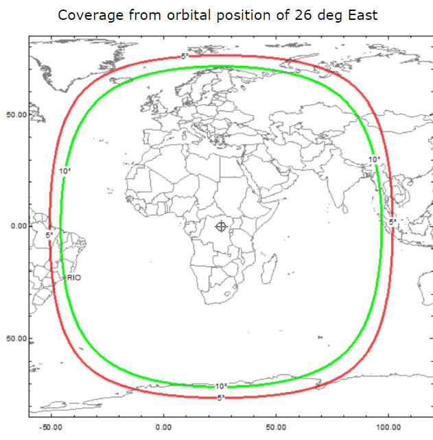
Image result for ao-100 coverage
OSCAR-100 (Es'Hail 2) is operational and looks to be working well, very well. I'd read on the web over three years ago that a geostationary amateur called Es'hail 2 was on the cards and after several years waiting it was launched from the Kennedy Space Center at 20:46 GMT on Thursday November 15th 2018 and has now taken up its orbit at 25.9 degree East.

This orbit gives coverage from northern Europe right across to Brazil and down to Thailand as you can see from the map on the right.


I'll have some of that I thought (amongst all my other projects !) and so here are my plans and what I've found out so far .......

The ground equipment required to receive is fairly basic (as satellite equipment goes) and the satellite itself has two “Phase 4” amateur radio transponders operating in the 2400 MHz and 10450 MHz bands. A 250 kHz bandwidth linear transponder intended for conventional analogue operations (Voice,CW etc) and an 8 MHz bandwidth transponder for experimental digital modulation schemes and DVB amateur television.


The BATC (British Amatuer Television Club) have been supporting this very strongly and have deployed a ground receiving station at Goonhilly (yes Goonhilly!!) which has two receivers online - one for the linear transponder (Here) and one for the wideband transponder (Here). Thanks to them for all their efforts - simply brilliant !


The linear (narrowband) transponder receiver works really well and I've heard many stations on it right across the foot print, including Brazil, Germany, UK, Austria, Belgium, Russia to name a few and so I got to thinking that I would like to build a setup to receive and transmit through it and take part in this great experiment!


The ground equipment (for narrow band work to start with) is fairly basic


For receive (X Band - 10Ghz downlink - Vertical Polarisation) - a standard satellite dish, LNB and SDR receiver).

For transmit (S Band 2.3Ghz uplink - Right Hand Circular Polarisation) - with a 5W nominal uplink power 

Dish first -  80cm is good enough although I heard someone using a 45cm for receiving!) and these are quite low cost - offset feed is acceptable and looks more like a neighbours dish !!

Next the LNB - The Es’hail 2 Amateur transponders are at 10.5GHz most common consumer LNBs (Low Noise Blocks) can be used to receive well below 10.7GHz with a 9750MHz local oscillator, so for Es’hail 2 I'll always use the 'standard' 9750MHz local oscillator. 

Virtually any standard LNB for satellite TV will do  - BUT it needs to have a PLL rather than a DLO - so it is more stable and wont drift - Octogon LNB's seem to be quite popular (and work well by the sound of it). This will need to have suitable voltage fed to it to switch the correct polarisation (+12v for Narrowband and for Wideband +18v) via a 'T' feed. I wont bother to detail the switching of the LO in the LNB (using 22Khz tone) as for my use it wont be needed - but that's how you switch from 9750Mhz to 10600Mhz (usually!!)  

This LNB acts as a down converter and so the desired signal for receive becomes :-

10.5Ghz - 9.75Ghz = 0.75Ghz or 750Mhz

The SDR receiver needs to cover this 750Mhz frequency - there are plenty of low cost SDR's out there but I wouldn't by too low cost - look at my choice of SDR at the end which might kill two birds with one stone !

That's the receive setup.

Next for transmit.

There are multiple ways to do this but almost all involve an up converter of some sort to take a baseband frequency - such as 144 or 432Mhz for the IF - mix it with a suitable oscillator and hey presto a 13cm (2.3ghz) tx signal at low power - add an amplifier and your nearly there.

One important point to remember is that you need the system to be full duplex - ie you need to be able to listen to your transmitted signal on the downlink at the same time as transmitting, and so that is why many people I assume seem to use an SDR based setup as well as a 144 or 432Mhz IF transmitter setup - or so it seems to me!

For the antenna you can use a separate antenna  - many WiFi yagis and parabolic antennas are available that will have enough gain / bandwidth. 

Another option is a dual feed to the dish, so only one antenna is needed - less hassle to align and put up but more hassle to sort the feed out.

So what will I be doing ?

I've started to put together the building blocks 
  • 80cm or preferably 100cm offset dish (to be purchased)
  • Octogon Quad feed PLL LNB (so I can modify it and add an external reference for extra stability if needed - Andy Talbot G4JNT describes a modification here for an external reference feed, and here is the BATC wiki page that details how to do it for using one of the Quad inputs - this is what I will do should I need to with a suitable external GPS linked reference @ 25mhz such as Leo Bodnar's GPD reference or something similar.
  • I have also got a dual feed on order when I'm ready to do the transmit side as I only want one dish and so have opted for the extra complexity on the feed side !
  • Or I can build a dual feed for the LNB there are several designs around


For the SDR element I've decided to experiment and go for an LimeSDR Mini - this is a full duplex (transmit and receive) SDR transceiver which cover from 10Mhz up to 3.5Ghz and so will also produce the required transmit signal on 13cm as well as simultaneously receiving at the required IF frequency of around 750Mhz.


Class A 30w 13cm Amplifier


On the transmit side I will use the LimeSDR Mini mini and have opted for 13cm class A Amplifier  that I found that can give upto 30W output from typically 10mW input. The LimeSDR Mini outputs 0dBm at 13cm so may well need a small amplifier in front but we shall see !


I received the LimeSDR mini this week - I've already connected it to my portable, added its drivers, plugged it into a suitable USB3 socket and then updated its firmware. All worked perfectly and I've just experimented receiving on 60M and 40M and it seem to work really well - its not really designed for HF but for higher VHF/UHF and SHF - I intend to check these out soon!

The software I've been using is SDRConsole V3 from Simon Brown G4ELI - this is truly a superb piece of software which does both RX and TX and has exactly the functionality that is required to operate with a down converter and synchronise the 13cm uplink so I think I will be using this in future !

It also supports the LimeSDR Mini natively so it makes it really easy to get working :)

I've already donated £50 as a start and will donate more as I use the software more - it really is worth it - superb from my perspective - Thanks Simon !!