Friday, 8 March 2019

OSCAR-100 - Es’hail 2 - My Approach

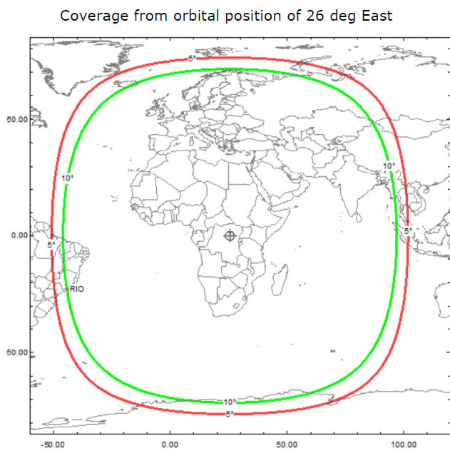
Image result for ao-100 coverage
OSCAR-100 (Es'Hail 2) is operational and looks to be working well, very well. I'd read on the web over three years ago that a geostationary amateur called Es'hail 2 was on the cards and after several years waiting it was launched from the Kennedy Space Center at 20:46 GMT on Thursday November 15th 2018 and has now taken up its orbit at 25.9 degree East.

This orbit gives coverage from northern Europe right across to Brazil and down to Thailand as you can see from the map on the right.


I'll have some of that I thought (amongst all my other projects !) and so here are my plans and what I've found out so far .......

The ground equipment required to receive is fairly basic (as satellite equipment goes) and the satellite itself has two “Phase 4” amateur radio transponders operating in the 2400 MHz and 10450 MHz bands. A 250 kHz bandwidth linear transponder intended for conventional analogue operations (Voice,CW etc) and an 8 MHz bandwidth transponder for experimental digital modulation schemes and DVB amateur television.


The BATC (British Amatuer Television Club) have been supporting this very strongly and have deployed a ground receiving station at Goonhilly (yes Goonhilly!!) which has two receivers online - one for the linear transponder (Here) and one for the wideband transponder (Here). Thanks to them for all their efforts - simply brilliant !


The linear (narrowband) transponder receiver works really well and I've heard many stations on it right across the foot print, including Brazil, Germany, UK, Austria, Belgium, Russia to name a few and so I got to thinking that I would like to build a setup to receive and transmit through it and take part in this great experiment!


The ground equipment (for narrow band work to start with) is fairly basic


For receive (X Band - 10Ghz downlink - Vertical Polarisation) - a standard satellite dish, LNB and SDR receiver).

For transmit (S Band 2.3Ghz uplink - Right Hand Circular Polarisation) - with a 5W nominal uplink power 

Dish first -  80cm is good enough although I heard someone using a 45cm for receiving!) and these are quite low cost - offset feed is acceptable and looks more like a neighbours dish !!

Next the LNB - The Es’hail 2 Amateur transponders are at 10.5GHz most common consumer LNBs (Low Noise Blocks) can be used to receive well below 10.7GHz with a 9750MHz local oscillator, so for Es’hail 2 I'll always use the 'standard' 9750MHz local oscillator. 

Virtually any standard LNB for satellite TV will do  - BUT it needs to have a PLL rather than a DLO - so it is more stable and wont drift - Octogon LNB's seem to be quite popular (and work well by the sound of it). This will need to have suitable voltage fed to it to switch the correct polarisation (+12v for Narrowband and for Wideband +18v) via a 'T' feed. I wont bother to detail the switching of the LO in the LNB (using 22Khz tone) as for my use it wont be needed - but that's how you switch from 9750Mhz to 10600Mhz (usually!!)  

This LNB acts as a down converter and so the desired signal for receive becomes :-

10.5Ghz - 9.75Ghz = 0.75Ghz or 750Mhz

The SDR receiver needs to cover this 750Mhz frequency - there are plenty of low cost SDR's out there but I wouldn't by too low cost - look at my choice of SDR at the end which might kill two birds with one stone !

That's the receive setup.

Next for transmit.

There are multiple ways to do this but almost all involve an up converter of some sort to take a baseband frequency - such as 144 or 432Mhz for the IF - mix it with a suitable oscillator and hey presto a 13cm (2.3ghz) tx signal at low power - add an amplifier and your nearly there.

One important point to remember is that you need the system to be full duplex - ie you need to be able to listen to your transmitted signal on the downlink at the same time as transmitting, and so that is why many people I assume seem to use an SDR based setup as well as a 144 or 432Mhz IF transmitter setup - or so it seems to me!

For the antenna you can use a separate antenna  - many WiFi yagis and parabolic antennas are available that will have enough gain / bandwidth. 

Another option is a dual feed to the dish, so only one antenna is needed - less hassle to align and put up but more hassle to sort the feed out.

So what will I be doing ?

I've started to put together the building blocks 
  • 80cm or preferably 100cm offset dish (to be purchased)
  • Octogon Quad feed PLL LNB (so I can modify it and add an external reference for extra stability if needed - Andy Talbot G4JNT describes a modification here for an external reference feed, and here is the BATC wiki page that details how to do it for using one of the Quad inputs - this is what I will do should I need to with a suitable external GPS linked reference @ 25mhz such as Leo Bodnar's GPD reference or something similar.
  • I have also got a dual feed on order when I'm ready to do the transmit side as I only want one dish and so have opted for the extra complexity on the feed side !
  • Or I can build a dual feed for the LNB there are several designs around


For the SDR element I've decided to experiment and go for an LimeSDR Mini - this is a full duplex (transmit and receive) SDR transceiver which cover from 10Mhz up to 3.5Ghz and so will also produce the required transmit signal on 13cm as well as simultaneously receiving at the required IF frequency of around 750Mhz.


Class A 30w 13cm Amplifier


On the transmit side I will use the LimeSDR Mini mini and have opted for 13cm class A Amplifier  that I found that can give upto 30W output from typically 10mW input. The LimeSDR Mini outputs 0dBm at 13cm so may well need a small amplifier in front but we shall see !


I received the LimeSDR mini this week - I've already connected it to my portable, added its drivers, plugged it into a suitable USB3 socket and then updated its firmware. All worked perfectly and I've just experimented receiving on 60M and 40M and it seem to work really well - its not really designed for HF but for higher VHF/UHF and SHF - I intend to check these out soon!

The software I've been using is SDRConsole V3 from Simon Brown G4ELI - this is truly a superb piece of software which does both RX and TX and has exactly the functionality that is required to operate with a down converter and synchronise the 13cm uplink so I think I will be using this in future !

It also supports the LimeSDR Mini natively so it makes it really easy to get working :)

I've already donated £50 as a start and will donate more as I use the software more - it really is worth it - superb from my perspective - Thanks Simon !!

Friday, 15 February 2019

Collins PM-2 - Diode replacement


Hi,

I mentioned that in the capacitor replacement blog I would be changing the diodes from 1N4192 to 1N4007 as they were higher specification with better PIV etc.

At the time of the capacitor blog writing the diodes whilst ordered from RS components hadn't arrived, the cost per component for (50 devices) was just 19.1p each or with VAT just under 23p each not bad for Vishay 1000V 1A diodes ! other suppliers are of course available but when possible I use RS components for all my orders - they are not the cheapest but the service is excellent and the quality of the components is a known quantity.

So a nice straightforward evening job.

Again please take care, ensure that all capacitors are discharged and of course the unit it unplugged from the mains - check both of these again before you start, also don't work on things when your tired. The voltages here can be lethal so here is the warning - if you choose to do this sort of work - you do so entirely at your own risk - the voltages here can be lethal and if you are not absolutely sure what your doing - don't - get someone else to do it who has the experience !

Here is the board in question prior to the work ;


Note the old 'top hat' diodes there are three 'sets' or areas for rectification - the one on the right is for the +800v line, the one on the left is for +275 volt line and then a single diode is for the -50 to -75 bias line.

So after some careful diode removal - I tested them all and they were all acceptable as diodes go however with the increased specification available with the 1N4007 it would be silly not to take advantage of the increased headroom and performance - future proofing it effectively !

Below is the result of a very gentle hours work, still a little 'fettling' to straighten leads etc - but overall very acceptable :)


 I then checked and re-checked the diode orientation to ensure i'd got it right. I then checked against the circuit diagram (i'm always cautious!).Even though it was a very straightforward task I used my variac to bring up the unit. No problems and fully functional as expected.

Below is the circuit diagram for those that are interested - this is for the 6th version and is like mine - there are at least two versions out there so make sure you get the right one !

For the observant amongst you - you will notice that I haven't swapped the dual section capacitor C7 (A & B) - this is multi section capacitor and when I checked it for ESR it was really very good - replacements are available from the US, when I need them I get them from KE9PQ (Mark Olson) who runs Nationwide Radio - gives excellent service. They are quite expensive though when the import tax and vat is added - but they are great quality !

So on balance I decided that I wouldn't replace it 

So that's the end of the PM-2 recap and diode replacement - I was lucky all the other components when I checked them were all well within tolerance and so I left them.  

I'll soak test the unit over the next couple of weeks and then I'm considering trying a circuit to regulate the 275V line - why ? - because the increased line voltages mean that all of these circuits were designed for 110v or 220V and we run close to 244 volts here occasionally and most of the time well in excess of 235V which means that all lines run high the 6.3v runs closer to 6.8v, 275 is close to 290. All of which can cause problems and shorten the life of the tubes.

This is a well known problem and there are several solutions out there for the collins 516F-2 power supply (I've got to update two of these and so will write that up when i do it)  - which involve 'bucking' the mains supply (using spare winding's to effectively drop the mains voltage) but there doesn't seem to be any for the PM2 hence my thinking to regulate the 275 line and examine the possibility of putting together something to reduce the line voltage without simply sticking a high wattage resistor in series (some peoples approach) which will increase the heat generated somewhat !!

73s for now
Chris
M1ABK

Wednesday, 13 February 2019

Collins PM-2 Capacitor Replacement


For those that I don't know I am an avid collector / repairer of Collins equipment.

I recently acquired a KWM-2a and a PM-2 to add to my other Collins equipment collection, I collected it and as per the advert both were in good condition and working quite well. Both were well looked after and the seller thought that they were both ex MOD units. Certainly the PM-2 unit had an MOD mod plate on it and so its likely that these were ex RAF. I wonder what service they did ?

After a thorough check over I decided that the PM-2 could do with capacitor and diode replacement, whilst it was working well and so no signs of misuse whatsoever to ensure a long and stable further life a change would be needed.

Now the warning - if you choose to do this sort of work - you do so entirely at your own risk - the voltages here can be lethal and if you are not absolutely sure what your doing - don't - get someone else to do it who has the experience !

For those that don't know - the PM-2 is a "lightweight" (!!) power supply that fixes to the rear of a Collins KWM2 / 2a transceiver, elements of it are very similar to the classic 516F-2 power supply but has solid state rectifiers not valve and in is not designed for high duty cycles - although in amateur use (other than RTTY etc) they can give really good service.

Capacitors are mounted on the top and bottom of the main chassis with the diodes on a point to point Bakelite/Phenolic board where diodes and other components are mounted (including two 10uF electrolytics on the rear of it)


So after some dismantling here are the electrolytics on the top of the chassis (they are under the speaker) - they were not in bad condition but clearly were original (1966 date code) - they are 100uF (450V) - modern electrolytics are quite a bit smaller and so I decided to replace with modern axial equivalents 


So after some careful work two new 100uF 450V capacitors were in put in place, with careful reuse of original insulation and where not possible micro silicone sleeving as used originally in later Collins equipment. As can be seen they are considerably smaller but have better specification such as ripple current etc.  


 Now onto the underside of the chassis - the two 100uf 450V capacitors are under the Phenolic board - the board is held by four screws two short ones goes into insulated standoffs and the longer ones go into the metal standoffs (don't get them mixed up as the long ones will damage or crack the insulated stand offs!) - you can see them in the picture left - as per the other capacitors whilst not in bad condition they were the originals and so well over 50 years old !


After some more careful work - new capacitors were in place again using the original insulation where possible and where not using silicone sleeving as per Collins later spec, as previously they are considerably smaller but with a better specification, this time I used two small cable ties to ensure that the capacitors don't move around at all (unlikely I know)

So onto the two 10uF 100V capacitors that are under the board (don't forget them!) - these were replaced with two 10Uf 450V capacitors - again these are substantially smaller with a higher spec - however please note - make sure that they are wired correctly (I know you always check like I do!) but as they are used in the negative bias supply they are 'back to front' with regard to ground - ie the +ve terminal goes to ground - follow the original connections very carefully and you'll be fine :)


And here are the new ones, smaller and certainly cleaner !I ordered the diode replacements for the 1N4192 diodes but they hadn't arrived at the time of doing this so I'll put together a short blog entry when they arrive, these will be replaced with 1N4007 diodes which I do with all Collins equipment power supplies - I've done this since reading an article in the Collins Collector Associations magazine (Signal) on the 30L1  amplifier by Bill Carns, N7OTQ which details the advantages.


Diode                                Forward Current    PIV           Rating Reverse leakage Package 
1N1492 (Original)                   750 mA         600 Vdc               300 microA max       Metal 
1N4007                                 1000 mA       1000 Vdc               50 microA                 Plastic

As you can see its a no brainer !

Some tips now - the bias pot collar should be removed to allow the pot to move (and be removed) as otherwise you may damage the cable connections to it (they are almost certainly brittle) - I did this but I still had to repair all three connections to the pot as they were virtually hanging off the control !

Another tip - when you complete each stage - check recheck and then check again you've done it right observing polarity of capacitors etc very carefully. I do this and then have a cup of coffee take a break and then check again. I usually will put it to one side and check the next day - even though I'm experienced I still like to take care - at best you'll destroy the components - at worst you'll damage something else and your confidence will take a bad knock - these things go bang quite nicely (and loudly!) - we've all done it - but lets avoid it if at all possible!

When all assembled and double checked (as per above) I then used a variac to bring up the unit - sometime this isn't viable due to the way they are designed - but usually it is.

Result - no smoke and correct voltages - the KWM2a worked nicely and is now waiting for the diodes to be replaced when they arrive ! 

Sunday, 10 February 2019

TS-790 PA failure repair


Long time no post !

I've been really busy with work and family and so whilst I've been doing work in the shack, carrying out repairs, restorations etc for other amateurs across the country, I've not had any time to write it up in the blog, I usually take some pictures of the work or restorations and so I will try to write them up as some may be useful or interesting to others, or perhaps the techniques used will be useful to someone !

A few things I've completed have been some repairs for other amateurs, including an interesting repair to a TS-790 which was diagnosed as a power block failure in the 144Mhz PA section (M67727). It was indeed a failure, however upon further investigation and very careful disassembly of the hybrid PA 'black block' which involved carefully removing the 'glue' to enable the top cover off - I discovered that the 2nd stage (Base bias ) connector leg was badly discoloured and had a very high resistance to the hybrid circuits substrate. After measuring it the leg actually fell off from the hybrid circuit substrate ! 

Unfortunately I can't find the picture of the failure that I took :( 

I then cleaned the area on the hybrid and the pin itself and successfully  re-soldered the leg to the hybrid circuit and after re assembly surprise surprise the power output returned to normal.

I've no idea why it failed in this manner although I have some thoughts.

It would seem that none of the PA blocks have any heat-sink compound between the hybrid units and the chassis (!) - no idea why but all that I've had through my hands to repair have been the same. So my theory is that the hybrids have hot spots and one of these is around the 2nd voltage feed into the hybrid to 144Mhz and this through heat cycling causes that area to fail either cracking the hybrid substrate or causing the pin to fail its connection.

So if you have problems with power drop off or failure - it might well be worth checking this and if your lucky and haven't - then I'd check of there is any heat sink compound on the PA blocks and if not - add some !!

Certainly with any hi duty cycle use or contest use I would not wish to use it without this update.

So another TS-790 returned to its owner aligned and working very well - result ! 

I wonder how many PA blocks have been changed as faulty (which technically they are!) when a relatively simply fix could have extended their life substantially - also the original blocks are fairly difficult to get hold and substitutes are getting more expensive - so certainly worth checking !

I hope this might be useful to other 790 owners

73s
Chris


Sunday, 25 June 2017

Yaesu FT-902DM "Restoration" Part Three

Hi,

So onto the second one the PB-1708A Rectifier A board.

Here it is ;


As you can see if you look carefully - overall not in bad condition but the two capacitor on the right look a slightly different colour and so that might indicate that they have a problem.

Either way they will get replaced with new quality 105deg electrolytics.


On the underside of the board (right) you will see the
 usual Yaesu soldering but look more closely. I've circled in red a 'blobby' or poor solder joint. Being entirely fair about it - it might have been due to heat but I think its been like this from the start 
So work starts - removed the four vertical electrolytics - again be careful they have the yaseu 'glue' to hold them still when the unit was subject to vibration when it was used mobile (!!!).


Here are the capacitors as removed, as you might be able to see the two on the left have a slight 'bulge' - they were the Atwo with the slightly different colour tops.


Below  is the ESR value for one of the axial capacitors removed from the board - as you can see not too bad with and ESR of 0.19 Ohms and 3473uF  but they will get changed anyway!


Here is the replacement capacitor an ESR of 0.06 Ohms and a capacitance of 3235uF.


Remember the bottom of the board - well after a little rework etc. this is what it turned out like :-


Not perfect but pretty good, I also cleaned and re-flowed the edge connectors, if you do this make sure that the re-flow is as thin as possible - or you might open up the edge connector in the chassis and cause intermittent problems. When I put any of the boards into the chassis I use the cleaning solution that I mentioned earlier to protect and ensure a good connection.

Finally here is the completed board :-


One final note - TAKE CARE with the insertion of the vertical capacitors !! - look at the above picture - this board is a little different - the capacitors are not all in the same orientation - check and re-check - as if you get this wrong it will not be pleasant !! - I also noted that the board itself has the orientation marked on the board - but you can't see them when you put the capacitors in - so checking is a bit difficult !! 


Tuesday, 13 June 2017

Yaesu FT-902DM "Restoration" Part Two

Hi,

After a little testing everything tested out pretty well, RX was sensitive and working well, all the controls worked nicely with no "scratchiness" at all or needing to "rock" switches to get them to work.

Anyone who restores or repairs older transceivers will recognise these problems ! - usually quite easy to fix with the appropriate specialised cleaners - Corrosion X - I first starting to use this when I noticed that the great Kenwood restoration guru Jim, KE7OAY used it - it is really very good!) put it in a dropper dispenser and it lasts for ever and DeOxit - I recommend not getting an aerosol but getting a dropper bottle or a 'pump action' bottle - a lot easier to user and doesn't 'spray' everywhere - wasting what is a very expensive liquid !

I'll use a combination of these on the switches and pots when I clean them up - I do when I'm restoring others equipment, as a preventative and restorative measure.

So after checking I decided to replace the bias and HT electrolytic's everything checked out OK after slowly bringing up the voltage (see previous post) but these components are over  30 years old so replacement with newer, better tolerance 105deg components with better voltage ratings where available will help to preserve the radio for another 30 years hopefully !!

So after taking precautions to make sure that the radio (and its electrolytics!!) were fully discharged and the transceiver not plugged into the mains - we begin......

So board PB1717 (Rectifier C Board) first -


Before Capacitor change
Having a really close look at this board - overall its in good condition. There was no real worries about the capacitors, although the middle capacitor on the lower row (you can just see it in this picture) did look a little discolored compared to the others, no sign of stress such as bulging sides or tops.

Other components looked in good condition, although as always with this age of Yaesu equipment (or at least the ones I've worked on) the components seem to have been inserted in the board by someone who wanted to get home early on a Friday afternoon, they are not vertical and overall pretty poorly placed.

You might think a little OCD (?) but actually vertical components help heat flow and aid reliability so I usually (very carefully!) align them.


So on to removing the capacitors. Yaesu put these capacitors in with a small amount of 'glue' around each one as the radio could be used mobile (!) and it was an attempt to stop vibration based failure.

My approach is to use my desolder station (a god send - if you regularly repair or restore get a decent one!) to remove the capacitors. I do one at a time and start with the big ones.


removed electrolytics


Not quite sure that the photograph (left) shows it but the capacitor on the right of the photo has a very slight 'bulge' on its base, the left hand one is flat, so perhaps just as well I took the trouble to power the transceiver up carefully and I'm replacing the capacitors !!

The white / yellow stuff is the glue that Yaesu used. The trick to getting the capacitors out of this stuff is to desolder the legs carefully from the PCB and check that the legs are free, and then carefully - very carefully gentle rock the capacitor back and forth - don't force it - you may crack or damage the PCB :( 


Just for 'fun' I thought i would check the ESR and capacitance using my Peak ESR+ tester (another great bit of kit!) - 


As you can see the ESR is .49 ohms and its capacity is just over 28uF - not too bad for a 30 + year old capacitor !!!

But I'm replacing it anyway.....


So here is a comparison to the replacement capacitor as you can see its value is pretty much spot on and the ESR is slightly better at .47ohms.

The more observant amongst you will notice also that it is a higher voltage rating - 400V rather than 350V.

If possible (without going mad) I like to up the voltage rating a little, and of course improve the temperature rating to +105deg - not sure what the original ones were but most probably +85deg. This will again help aid reliability and longevity


I wont bore you with lots of pictures of removed capacitors etc.

Remember to clean the 'glue' residue off the board before mounting the new capacitors, I use a combination of a PCB 'tooth' pick tool and a little PCB cleaner - works well.

The board has the polarity of the capacitors marked with + and - , so be sure to follow those correctly, if your thinking of doing this - you'll know that the white stripe (with the - marking!) points to the minus lead - this is also the shorter of the two leads (but don't always rely on that - sometime they are trimmed incorrectly!!)

So what was the result for the Rectifier C board ?


Finished board
Again the more observant will note that I haven't change the axial capacitor at the right of the board - simple reason is that I didn't have one in stock ! - I checked it using the peak ESR+ meter and its ESR and capacitance was fine so I decided to leave it. I've order some new ones and when they arrive I'll replace it.

On a final note - always use the best capacitors you can find, a brand name like Rubycon, Nichicon (which I try to use) etc. - others may disagree

A word of caution though - use a reputable supplier - they're are fakes out there and eBay is awash with 'good value' components. I only purchase through RS Components - they might be a little more expensive (in some cases they are a lot cheaper!) but the peace of mind is priceless - especially if your doing the work for someone else !!

Now onto the next board ........ 


Saturday, 10 June 2017

Yaesu FT-902DM "Restoration" Part One

Hi,

I Often get offered equipment to repair directly, and as you know (if you read these occasional blogs!) I haunt eBay and few other forums looking for my favourite equipment, Heathkit, Drake, Collins as well as for interesting equipment that needs repair or as its known to most advertisers "Needs TLC" or "Untested - no power supply" - all of which general means - either "I've tried to repair it and I've failed" or "I've let somebody have a look at it and it came back worse than it left" or (very occasionally) people are genuine and absolutely truthful about the equipment or situation.  

We this one is an example of exactly the last one.

I was looking on one of the forums and noted a posting about an FT-902DM with Speaker unit, FC-902 ATU and a FTV-901R transverter. These were part of a silent key estate and the seller had been let down multiple times by people offering to buy and then not turning up or making an excuse. This advert said quite clearly that they had not been powered up as the seller was worried that they hadn't been used for sometime and he knew that to just 'turn them on' was a mistake (literally a big bang approach in many instances!) and he didn't have a Variac or such to do it properly so he'd left them.

Well that's a good start I thought - at least he cares and knows enough not to just turn them on. After some email exchanges and a few pictures - which showed them as in reasonably good physical shape but very dirty and unloved, I decided to purchase them. 

I've done many re-capping / restoration /  of Hybrid transceivers for other people and I have a modern 'Digital Variac' as well an 'old' style' one for just such purposes (often used for Drake and Collins kit!)  so I thought I'd give it a go for myself for a change.

True to form, I travelled to his QTH and met the gentleman selling them, he was honest as the day is long, the kit was exactly as he described and even had manuals for all the units - no interconnecting cables (but he had mentioned that) and also no rear AUX plug (remember with this or the right pins (1 and 2) being linked together the heaters wont work on the PA so no output). The 902DM did have the all important mains cable and plug though - this is good as they are increasingly hard to find and command quite huge amounts of money if they come up (£100+ !!!)

Anyway money exchanged hands and I was the proud owner of my own FT-902DM setup.

Here's some pictures of the lineup, not sure if it really comes across on the pictures how dirty and grimey they were, not the fault of the gentleman selling them I think but they way they were stored prior to him, in a garage would be my best guess.

 From the front looks good, dirty and grubby but no real marks on the from panel, all the controls work quite smoothly and the tuning dial at least moves (although you can't tell from the picture) but it did 'bind' a little on the rear skirt - possibly it had received a knock at some time - hope the VFO and the display works! - These are notorious for the counter chip going u/s - I've replaced a couple with a great kit from a Japanese amateur Teruhiko Hayashi ( JA2SVZ ) just google it if you need one.


As you can see from the picture right - this shows some of the grubbiness of the front panel / knobs etc. Nothing really to worry about on that front some ultrasonic cleaning should have them pretty much as good as new


The FC-902 looked good although as grimey and dusty as the others as well, all the knobs were there and they all moved fairly well the band switch moved with a satisfying 'clunk' - I've repaired one where this wasn't the case and it had caused arcing on the switch - it had lost one of it bearings and it caused the switch to have a very 'sloppy' action - possibly causing the issue. No such problem with this one :) 


Another picture showing how dirty it was


The FTV-901R transverter - again fairly dirty - this one was fitted with what I think was the standard 144Mhz plug in and no others
The other side of the unit


And finally the speaker unit - this isnt the right one for 902 range but was part of the lineup as it arrived. It has a white fascia edge and so is most likely an Ft-101 one. It also has a modified front panel with a fairly crude (and not central!) 3.5mm headphone socket. It is of the right impedance though and so is a worth keeping in my view - the right size etc.


So after introducing the kit - what next?

Well power it up of course !

As mentioned earlier if you have no idea of the provenance of the equipment - when it was last used or how its been stored - DO NOT JUST PLUG IT IN A TURN IT ON !!!

I would strongly recommend that you use a variac to slowly step up the voltage giving time at each step for the capacitors to re-form if needed, I would further recommend that when you have done this (I'll go through the steps I use in a moment) that you use a 'dim bulb tester' as well (not sure what one is then perhaps don't do this work - but if your interested then there a link here which explains what it is and who to build one.

I also power all my equipment via RCD breakers as well as test devices such as this radio.

I do this with all equipment - valve or otherwise - as its best to be careful.

So my regime is pretty much this (other will have their own which is no doubt better but this works for me).

1 - Check that the radio is configured correctly for the voltages (you'd be surprised how ofther this isn't the case!) - for this 902DM the case needs to be removed and the connections on the transformer checked - others might be different.

2 - When you have the case off - have a very careful look inside - look for damaged components - especially look at the capacitors in the PSU and bias areas - if need be remove casings or PCBs to do this (especially the case in hybrid radios like this one) - if there is no evidence of damage, overheating or capacitor stress (such as bulging or weeping) then move onto 3 - if in doubt don't power the radio - replace the capacitors. Also remember Capacitors can store charge for long time and so use a 'chicken stick' to discharge capacitors especially HT side if your unsure. here's a link to one if you don't know what one is here - again if you don't know about this - ask yourself should you really be doing this !! 

3 - Re-check number 1 and 2 - do this after a break (preferably the next day)  - remember these voltages can be lethal!

4 - Time to start applying voltages, I start at 25V then step to 50V, 75V, 100V, 150V, 175v, 200V and final 235V. I leave about 30 minutes at each stage, remember this is not a quick job - take your time. My electronic variac has a current meter as well - I would suggest you also have some method of checking current consumption. Don't forget to turn the radio on when you do this (!!!!)

5 - At each step watch carefully the current consumed and look and listen for any signs of stress with the radio or anything unusual such as smell etc. If current starts to rise quickly then stop - turn off and find the reason.

6 - When you finally get to the full mains voltage - leave it on and let it settle down for at least 90 mins.

7 - Finally remove the Variac (turn everything off first including the radio !) and then connect the dim bulb tester before you switch the radio on for the first time without a variac. Then switch the radio on - the dim bulb tester will glow brightly and then should settle down to a glow and the radio should power up. If the bulb stays bright you have a problem - the radio is drawing to much current - check whats causing it. 

8 - Finally start testing the unit and realignment etc. - and don't ever forget that there are lethal voltages in the radio - its bite might be fatal !

Finally a note of caution (and a disclaimer) - if you do work like this (and possibly follow my instructions) you do so at your own risk I will not be held liable in anyway whatsoever. I know what I'm doing and the risks - every radio is different - so proceed with great caution and at your own risk - if your not sure the don't do it and let someone who knows what their doing - do it !! remember these voltages can be lethal - its not 12V !!!


So if your got this far - well done - sorry for the disclaimers but these can be dangerous radios and I'd hate for anyone to hurt themselves.

After doing all that on the FT-902DM what happened ????


Well I'm pleased to say that it came up fine - no bangs or capacitor problems - display came up fine, meter bulbs and VFO backlight worked (!) - and audio from the speaker as well.

It tuned ok on all bands and peaked signals nicely on the pre-selector.

I will be replacing the HT and Bias electrolytics on the rectifier boards as the next step - in the meantime I will start testing and see what else needs doing. I may well recap the whole radio but the HT and bias are the most important - even if it did power up no problem after all my trouble to carefully step up the voltage - you never know though so take care !!

Overall a great result so far !!!

73s
Chris